


|
|
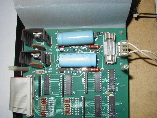
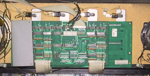
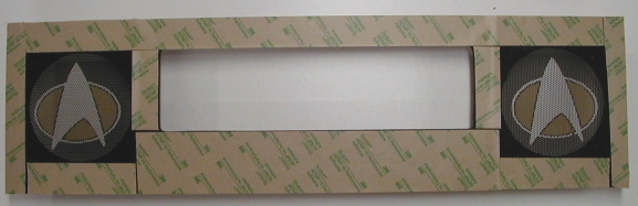
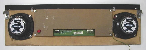
Wooden Display Panel Speaker Replacement - Alphanumeric DisplaySafety tip: Be sure to disconnect the power to the game before performing any work! In order to replace the speakers the display panel must be removed from the game; you'll need to disconnect a few cables to do this. Before disconnecting any cable it's always a good idea to mark its position so the cable can be replaced properly. Make a mark on the pin 1 end of the connector and socket, and label the connector with the mating socket number. Hint: In the sections below you'll need to find the center of a square. It's very easy to do this by drawing diagonal lines from each corner of the square to the opposite corner using a straight edge and a pencil. The point where the two lines intersect to form an "X" is the center of the square. Safety tip: Wear eye protection when using power tools! A dust mask will come in handy for the operations that generate lots of dust. Remove the Display PanelRemove the translite panel assembly and set it in a safe location. Lift the display panel upward to free it from the upper mounting brackets and set the panel face down on a towel or other padding laid on the playfield glass. Follow the black and black-yellow wires from the left speaker into the back box to identify the specific connector on the sound board, and then remove that connector from the board. The speaker wiring harness will also have a single contact in-line connector that joins the display panel speaker wiring harness to the cabinet speaker wiring harness; you'll need to disconnect this connector as well. Now you can unravel the display panel speaker wiring harness from the back box wiring harnesses and cable clamps. Remove the power and data cables from the rear of the alphanumeric display board; don't forget to mark the pin 1 position of the power and data cables first! Note that one of the power cables is located under the insulating paper (also known as "fish paper") that covers the high voltage section on the left side of the display board.
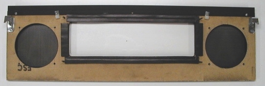
It's easier to reach the connector if you fold the insulating paper back from the nylon stand-offs; just squeeze the split top edges of each nylon stand-off while carefully pulling up on the paper. If the game has feature lamps mounted along the bottom edge of the display panel (The Machine: Bride of Pinbot), follow the wiring from the feature lamps into the back box to identify the specific connector on the power driver board, and then remove that connector from the board. Remove the nut from the threaded stud on the left inside bottom corner of the back box, and then remove the green-yellow ground wire leading from the display panel. Now you can remove the display panel from the game. Disassemble the Display PanelSet the display panel on a padded work surface. Cut the black and black-yellow wires from the speaker wiring harness where they attach to the left speaker; you can discard this harness, as we'll be replacing it with a new one. Also cut the two wires (black and black-yellow) that run from the left speaker to the right speaker. Most games will have a coil wired in parallel with the right speaker; you can cut these wires where they connect to the right speaker. Remove Alphanumeric Display, Speakers, and Feature Lamp SocketsIf there are feature lamp sockets mounted to the rear of the display panel (used on The Machine: Bride of Pinbot), remove the mounting screws and set the lamp sockets aside.
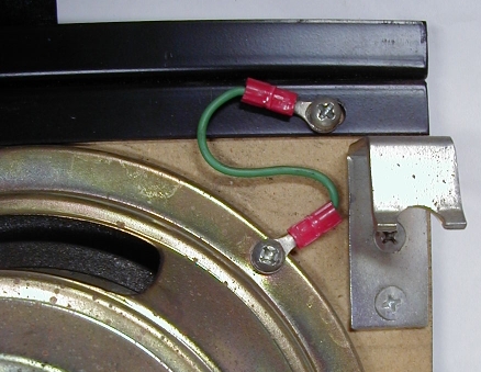
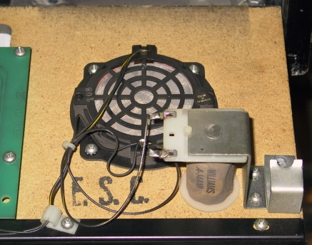
Remove the four screws that fasten the alphanumeric display board to the wooden display panel, and then remove the display board (note that the left two mounting screws are hidden by the insulating paper in this picture). Store the display board face down on a towel or other padded material. Set the mounting hardware aside for later re-use. Remove the four screws that mount each speaker to the display panel, and then remove each speaker. The left speaker will have one green-yellow ground wires fastened under the lower screw closest to the left edge of the panel; save that for later re-installation. The U-channel on the top edge of the display is made of either metal or plastic; if it's metal there will be a short green-yellow jumper wire from the speaker mounting screw to the left-most screw that fastens the U-channel to the panel.
Keep the speaker mounting screws; you will probably be able to re-use them. If there is a coil assembly mounted next to the right speaker cutout remove the two screws that mount the assembly to the panel, and then remove the assembly. You can discard the coil assembly as we won't use it in the new installation.
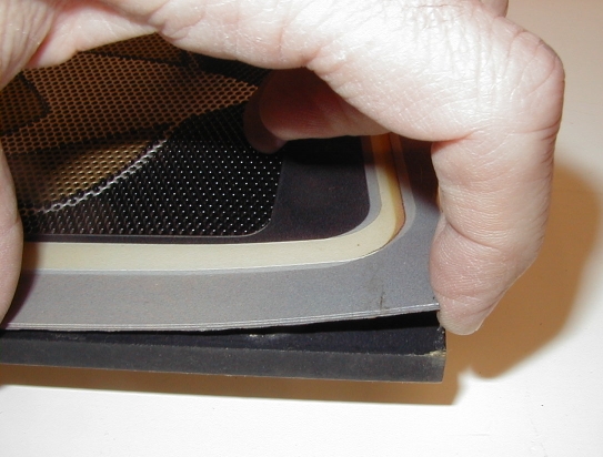
Remove Mounting HardwareRemove the two screws that mount the two J-shaped hooks used to mount the top of the display panel to the rails inside the back box, and set the screws and hooks aside. Remove the four screws that mount the metal or plastic U-channel to the top of the display panel, and set the screws and U-channel aside. Note that the inner two screws have small cable clamps on them; don't lose the clamps. Remove Screened Plastic PanelNote: The illustrations in this section are from a dot matrix display panel. The screened plastic panel on an alphanumeric display is removed in the same manner. Now comes the tricky part: removing the screened plastic panel from the front of the wooden display panel. The plastic panel is fastened to the wooden panel by double-sided foam tape that usually has lost much of its stickiness, but you may have to gently pry the plastic panel to peel it away from the wooden panel. Do not use any kind of sharp object such as a screwdriver, putty knife, or scraper; pry only with your fingers! Don't use a heat gun on the plastic panel, as it may deform the panel. If you start at one corner and maintain gentle pressure the adhesive should break free; some times quite easily, and some times it will be a real struggle. Take your time and don't bend the plastic panel too sharply; if you crease the plastic it's almost impossible to remove the crease.
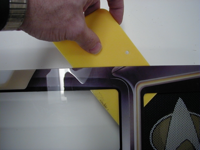
If the adhesive is hanging on for dear life there are a couple of things to try. First, put the entire display panel in a refrigerator for about 20 minutes; the cold can make the adhesive less sticky. If that fails, try using a hair dryer set on the lowest heat level and warm the stubborn area of the panel; don't leave the heat on any one spot too long, and don't use a paint stripping heat gun - it will produce too much heat. Finally, if all else fails, you may have to resort to using a plastic scraper to help cut through the adhesive. The kind sold for use with auto body putty is ideal: soft enough not to damage the screening on the plastic panel, but stiff enough to cut through the adhesive. The trick is to maintain gentle, even pressure until the adhesive bonds break. Don't force it, don't rush it, and be extra careful!
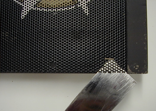
Set the plastic panel in a safe place once it is free from the display panel. Remove Speaker GrillesThe metal speaker grilles on the display panel are held in place by small nails or staples near the four corners of each speaker grille. Insert a flat putty knife between the speaker grille and the panel and gently pry up the corners of each grille; the nail or staple should pull out of the wooden panel without too much force. Be careful that you don't pry too hard and consequently bend or distort the speaker grilles! Also be careful that you don't lose the nails or staples while prying; they have a tendency to pop out.
Remove Speaker Mounting HardwareThread one of the longer speaker mounting screws a few turns into one of the four T-nuts around the smaller cutout in the display panel, and then tap the screw head with a hammer; the T-nut should pop right out. Repeat for the remaining T-nuts. Set the T-nuts and screw aside for re-use later.
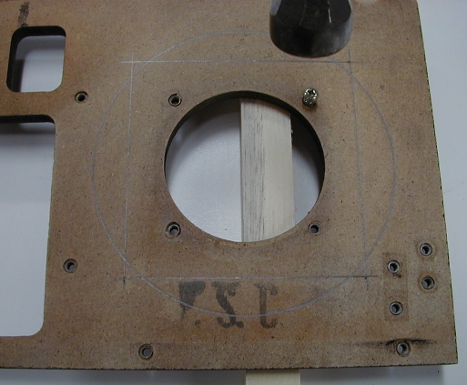
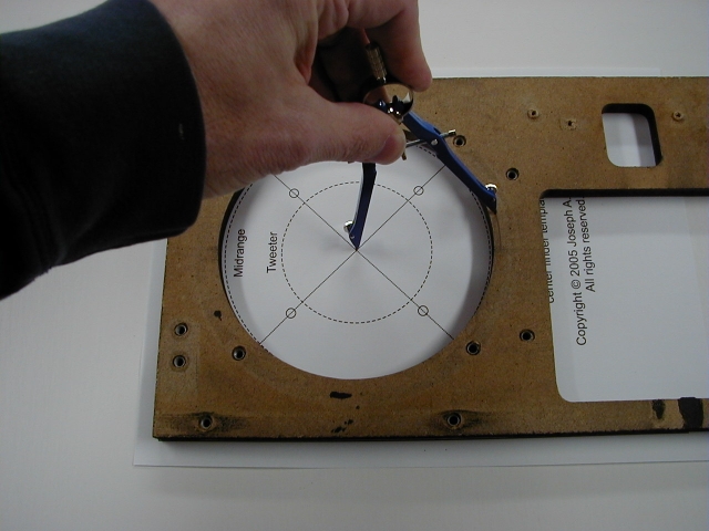
Modify the Display PanelWe'll enlarge the smaller (right) cutout in the display panel to accommodate a 6-1/2 inch speaker, and also drill new mounting holes for the T-nuts that mount the speaker. You'll probably also need to enlarge the larger (left) cutout; while the existing mounting hardware locations on the left cutout match up with those used on a 6-1/2 inch speaker, the cutout is only 5-3/8 inches in diameter. This is somewhat smaller than the more common 5-5/8 inch diameter of a 6-1/2 inch speaker, and the smaller hole will probably interfere with movement of the speaker surround. When you're done the left and right sides of the display panel will have identical cutouts - that is, if you've measured carefully! Don't forget the old adage about measuring twice before you cut once: that's especially important when you're modifying the display panel. This is a diagram of the layout lines marked around the right speaker opening; the display panel is face down with the top edge toward the top of the diagram, so the cutout that will be modified is to your left as you look at the display panel:
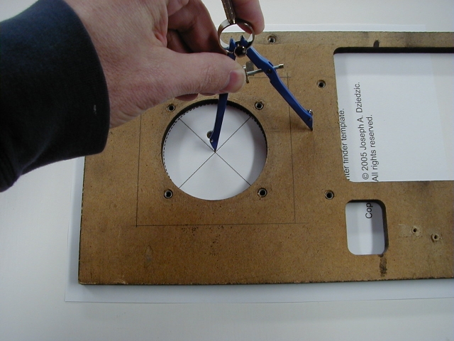
Take extra pains to position the layout lines exactly as specified; most of the 6-1/2 inch speakers I've used don't have elongated mounting holes for the mounting hardware, so you need to be very accurate when marking and drilling the new mounting holes. You will get the best results when you locate the mounting holes by using the measurements described below. However, you could use the "center finder" template described a few paragraphs down the page; place the template on the rear surface of the wooden display panel, line up the edges, and use an awl or a sharp nail to make marks where the four mounting holes will be drilled. If you use the template be sure to double-check the positions of the marks by measuring as described below. Using a combination square make a mark on the rear of the wooden display panel above the existing cutout 1-19/32 inch from the top edge of the panel. Make another mark below the existing speaker cutout 1-19/32 from the bottom edge of the panel.
Using the combination square draw a horizontal line through each of the two marks. In a similar fashion, make a mark to the left of the existing speaker cutout 1-19/32 inch from the left edge of the display panel. Make another mark to the right of the existing speaker cutout 5-29/32 inch from the left edge of the display panel. Using the combination square draw a vertical line through each of the two marks.
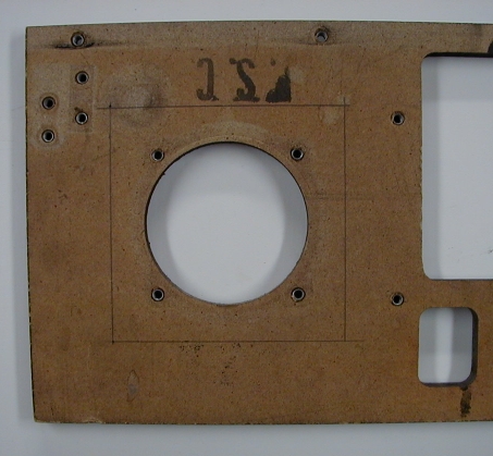
Your display panel should now have a square drawn on the left side. The corners of the square will be the places where the new T-nut mounting holes will be located.
Double-check your layout by placing the original 6 inch speaker on the rear of the display panel so the four speaker mounting holes are located at the four corners of the square; if your measurements were correct you should be able to see the corners of the square centered in each speaker mounting hole.
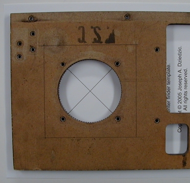
If you can't position the speaker so the four mounting holes line up with the four corners of the square, double-check the placement of the horizontal and vertical lines. Once you've verified your measurements drill 7/32 inch diameter holes at the four corners of the square; use a brad-point drill bit so you can position the bit exactly at each corner. Now we have to locate the center of the new cutout for the new speaker. To help I've created a "center finder" template that you can use. Click here to open the template in your browser, and then select the File -> Print menu item. Be sure the "page scaling" option is set to "none" so the template prints in the exact original size. Note: You must have Adobe® Reader® installed on your computer to view or print this file. Adobe® Reader® is available for free download on Adobe's Web Site. *CHECK FAKE TEMPLATE DIMENSIONS* (If you're unable to print the template it's pretty easy to make your own simplified version. Cut a piece of stiff cardboard 7-1/2 inches square. Draw a diagonal line from each corner; the point where the lines intersect to form an "X" is the center of the square. Using a compass draw a 2-7/8 inch circle centered on the "X". Now cut a 1/2 inch wide strip off one end of the template. When properly positioned the circle on the template will line up with the existing cutout in the panel, and the diagonal lines should line up with the new mounting holes you just drilled.) Slide the template under the display panel and align the three outer lines with the outside edges of the display panel. When properly aligned the smaller circle should be centered on the existing cutout, the new mounting holes you just drilled should line up with the circles on the dotted diagonal lines, and the four circles outside the smaller circle should line up with the original speaker mounting holes. Use some masking tape to fasten the template to the bottom of the display panel once you're satisfied with the alignment.
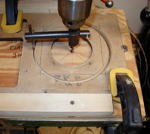
If you're using a circle cutter adjust it to make a 5-5/8 inch diameter hole. Securely clamp the display panel to the table of the drill press before starting the drill press! Position the pilot bit where the two diagonal lines intersect and slowly advance the circle cutter until it has cut through the entire thickness of the board. Stop as soon as the cutout section of MDF board starts to spin around with the circle cutter bit.
Note: You may want to use a 1/4 inch brad-point drill bit to make a pilot hole before using the circle cutter; the pilot bit on the circle cutter is a standard drill bit that is a little tough to align exactly even with the center lines on the template. If you're using a jig or sabre saw, use a compass to mark a 5-5/8 inch diameter circle on the rear of the display panel; put the compass point on the "X" on the center-finder template. The circle you drew should be exactly centered around the outside of the existing cutout; once you've verified the position of the new circle remove the template.
In a similar fashion, mark a 5-5/8 inch diameter circle on the rear of the display panel around the left speaker cutout. We have to enlarge the left speaker cutout by about 1/4 inch to accommodate the surround of the 6-1/2 inch speaker.
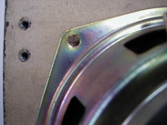
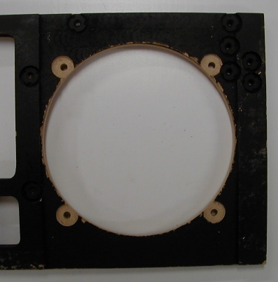
Drill a pilot hole for the saw blade just inside the circle, and then carefully cut along the line using the jig or sabre saw. Use a fine-toothed wood cutting blade so the cutout edges are smooth, and favor the inside edge of the line when cutting so the cutout isn't too large. Take your time and try to make the cutout as close to a perfect circle as you can. Working from the front side of the display panel (the side with the recesses for the speaker grilles) use a Forstner bit to drill a 5/8 inch diameter recess centered on each of the 7/32 inch holes you just drilled. Don't drill too deep! The recess only needs to be as deep as the round metal "head" of the T-nut; about 1/16 inch is usually deep enough. Look at the recessed holes for the T-nuts that mount the other speaker; you'll want to match that depth. If you don't make the recesses deep enough the T-nuts will rattle and buzz against the rear side of the metal speaker grilles. If you don't have a drill press you can use a router with a flat bottom bit to make the recesses. Here's a picture of the completed modifications to the right side speaker cutout as viewed from the front side of the display panel:
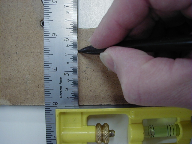
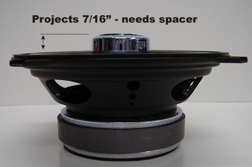
Tap the original T-nuts into place in the recesses with a hammer. If you removed the display mounting studs replace those and tap them into place with a hammer. Use flat black paint to paint the areas of exposed wood around the new speaker cutout; bare wood will be visible through the metal speaker grille. If any of the paint on the front surface of the display panel was pulled off when you removed the screened plastic panel be sure to paint the front surface of the display panel too. Check if You Will Need SpacersGrab one of your 6-1/2 inch replacement speakers and set it on the magnet end so the tweeter is facing upward. Carefully lay a flat metal ruler or straight edge across the outside edge of the speaker next to the tweeter. Measure the distance from the bottom of the ruler or straight edge to the top surface of the tweeter. If this distance is more than 5/16 inch you'll need to fabricate spacers for each side of the display panel. For example, the tweeter on this speaker projects 7/16 inch - it will need a spacer:
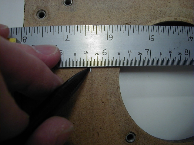
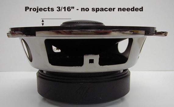
The tweeter on this speaker projects 3/16 inch - it will not need a spacer:
If you don't need spacers skip to the section on assembling the display panel. If you do need spacers, you may be able to use the ones that are typically included in the box with the speakers; you'll probably have to do quite a bit of surgery with a saw to get them to fit. You may prefer to simply fabricate spacers instead. Fabricate SpacersThe spacers are fabricated from 1/4 or 3/8 inch thick MDF board; the thickness used depends on the front projection of the tweeter. Measure the projection of the tweeter (see above) and subtract 1/4 inch. If the remainder is less than 1/4 inch you can use 1/4 inch thick MDF board; if the remainder is more than 1/4 inch you'll need to use 3/8 inch thick MDF board. Here is a diagram of the spacer that we're going to fabricate:
Cut a piece of MDF board 6-1/2 inches square. A table saw is the best tool for this job; if you don't have a table saw you can use a portable circular saw. You can also have your local lumber dealer cut some pieces of MDF board to size for you. MDF board is relatively inexpensive, and it usually costs an extra quarter or fifty cents per cut for the lumber dealer to cut the MDF board to size. Draw diagonal lines from each corner of the board to its opposite corner; the point where the two lines intersect to form an "X" is the center of the board. Make marks on each diagonal line 3-1/16 inch from the center of the square (four marks total). The screws that mount the speaker to the display panel will pass through holes at these points. Use a compass to mark a 6-1/2 inch diameter circle centered on the board; we will trim the spacer along this line later. If you're using a circle cutter adjust it to cut a 5-5/8 inch diameter circle. Be sure to securely clamp the MDF board to the table of the drill press before starting the drill press! Position the pilot bit where the two diagonal lines intersect and slowly advance the circle cutter until it has cut through the entire thickness of the board. Stop as soon as the cutout section of MDF board starts to spin around with the circle cutter bit. Note: You may want to use a 1/4 inch brad-point drill bit to make a pilot hole before using the circle cutter; the pilot bit on the circle cutter is a standard drill bit that is a little tough to align exactly even with the center lines on the template. If you're using a jig or sabre saw, use a compass to mark a 5-5/8 inch diameter circle centered on the board. Drill a pilot hole for the saw blade just inside the circle, and then carefully cut along the line using the jig or sabre saw. Use a fine-toothed wood cutting blade so the cutout edges are smooth, and favor the inside edge of the line when cutting so the cutout isn't too large. Take your time and try to make the cutout as close to a perfect circle as you can. Drill 3/16 inch diameter holes at the four points marked on the two diagonal lines. Use a jig or sabre saw to carefully cut just to the outside of the larger circle marked on the spacer. There is very little clearance around the sides of the speaker frame so it is necessary to cut the spacer to precisely match the diameter of the speaker frame. Here's what the spacer should look like when you're done drilling and cutting:
Place the spacer in position on the rear of the display panel and verify that the holes you drilled line up with the T-nuts inserted in the display panel. You may want to thread the four mounting screws originally used for the left speaker through the holes in the spacer to be sure the holes will line up properly when you mount the speaker. You may also want to temporarily re-attach the J-shaped hooks that mount the speaker panel to the back box rails to be sure the spacer clears the hooks. You may need to trim the spacer to clear the corner of the hooks. After you've verified the fit of the spacer you should paint it with flat black paint so it blends with the display panel (when seen from the front side of the panel). The completed spacer should look like this when placed in position on the display panel:
Assemble the Display PanelYou will need to purchase some #8-32 round head machine screws of the correct length for mounting the two replacement speakers. The original screws used are known as "SEMS fasteners"; they are basically a machine screw with a captive internal tooth lock washer. If you have access to a well-equipped hardware store you might be able to find SEMS fasteners in their screw department; I've also found these at Home Depot. If you can't find the SEMS fasteners you can use a regular #8-32 machine screw with a #8 internal tooth lock washer instead. You will probably need #8-32 x 1/2 inch screws if you're not using a spacer, and #8-32 x 3/4 inch screws with a spacer, but we'll determine the proper length next. Determine Speaker Mounting Screw LengthsMeasure the thickness of the speaker frame at any of the four mounting holes, add 1/4 inch to this measurement if you're using a spacer, and then add 1/4 inch to obtain the length of the new speaker mounting screws that you'll need. Machine screws are commonly available in 1/4 inch incremental lengths; use the shortest machine screw that does not exceed the total measurement. Depending on the particular model of speaker you use it may be necessary to add a few washers as spacers between the speaker mounting lugs and the surface of the display panel or spacer. Nylon washers are easier to use as they're not magnetic and won't be attracted to the speaker magnet; metal washers work fine but require a bit of patience to install. Temporarily mount one speaker at either position with two screws to check that the screws do not extend beyond the surface of the T-nuts inserted into the wooden display panel when the screws are fully seated; if you're using a spacer that should be in place when you mount the speaker. If the speaker mounting screws are too long you'll need to find some shorter ones, or cut the excess length off the ones you have. Remove the speaker once you've verified the length of the mounting screws. Replace the Speaker GrillesPlace the display panel so the recesses for the speaker grilles are facing upward. Set each metal speaker grille in position and carefully replace the small nails or staples that were originally used to mount the grilles. Check the orientation of the grille if there is a logo or printing on the front surface; no sense installing it upside-down! If you lose or misplace any of the nails or staples you can find some 1/4 inch long fine-gauge nails at your local hardware store. The original staples that were used are 22-gauge 3/8 inch wide crown 1/4 inch long; these are commonly known as upholstery staples, and are driven into place by an air-powered stapler. Re-attach the Screened Plastic PanelThe best way to re-attach the screened plastic panel is to use 3M 467MP high performance adhesive. If you're going to be upgrading the speakers on several games you may want to buy a roll of the 2 inch or 3 inch wide material. The 467MP can be used for re-adhering under-ramp decals, miscellaneous labels, and drop target decals. It's handy stuff, and if you do a lot of pinball restoration work you'll find plenty of ways to use a roll. You'll want to stick the 467MP on every surface of the wooden display panel that touches the screened plastic panel, including the top and bottom of the metal speaker grilles. When covering the speaker grilles don't run the adhesive beyond the speaker cutouts; check against the amount of area cut out of the screened plastic panel around each speaker grille. Try to cover sections with long strips of the 467MP to make it easier to remove the backing paper when you're ready to re-attach the plastic panel, but don't overlap any of the strips.
Rub the 467MP down firmly with your fingers or a roller; you want to get a secure bond so the adhesive stays behind when you remove the backing tape. Once all the lengths of 467MP are in place let the display panel set for several hours, or overnight, before you try to remove the backing tape from the 467MP. You may wish to lay the panel face down on a towel and add some weights to the back of the panel to help adhere the 467MP. Restoration tip: While you're waiting for the 467MP to set it's a good time to polish the front surface of the screened plastic panel and thoroughly clean the "window" in the plastic from the back side to remove any gunk. Carefully remove the backing tape from all of the 467MP on the wooden display panel. Double-check the orientation of the screened plastic panel to be sure you install it right side up! Slowly lower the plastic panel onto the front of the wooden display panel, taking extreme care to line up the edges of the plastic and wooden panels. Replace Panel Mounting HardwareReplace the metal or plastic U-channel and cable clamps that you removed from the top of the display panel. The U-channel is mounted to the wooden display panel with four #8-32 x 3/8 inch SEMS fasteners; small cable clamps are used at the two mounting positions closest to the center of the panel. If a metal U-channel is used it will have a ground wire secured under the screw near the left edge of the display panel. Replace the J-shaped hooks used to mount the top of the display panel to the rails inside the back box; they're held in place by a pair of #8-32 flat head machine screws. The rounded part of the hook should be closest to the plastic U-channel at the top edge of the display panel.
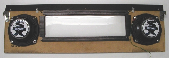
Mount Replacement SpeakersWhen you mount the replacement speakers the terminal lugs should be positioned toward the top edge of the display panel (the top is where the U-channel is mounted). Don't use excessive force when tightening the replacement speaker mounting screws. If the speaker has mounting lugs that extend from the sides of the speaker basket be sure to put some spacers (#8 flat washers work fine) between the lugs and the spacer or display panel; this way you won't distort the speaker basket when tightening the speaker mounting screws. Nylon washers are easier to use as they're not magnetic and won't be attracted to the speaker magnet; metal washers work fine but require a bit of patience to install.
The left speaker should have a green-yellow ground wire fastened under the lower mounting screw closest to the edge of the panel. If a metal U-channel is used there should be a short green-yellow ground wire connecting the channel to the upper mounting screw closest to the left edge of the panel. *UPDATE PICTURES*
Replace Alphanumeric Display and Feature Lamp SocketsPlace the alphanumeric display board in position on the rear of the display panel. The long edge of the board with two ribbon cable connectors should be oriented toward the top edge of the display panel (facing toward from the plastic U-channel on the top edge of the panel). Replace the four screws that secure the display board to the panel. Don't use excessive force when tightening the display mounting screws.
The last step is to re-install the feature lamp sockets on the display panel if used on your game (The Machine: Bride of Pinbot). We're done with the display panel for now; we'll wire it up after we're done with the cabinet speaker.
NEXT: cabinet speaker replacement HOME: WPC speaker replacement
Copyright © 2005 by Joseph A. Dziedzic. All rights reserved. |