


|
|
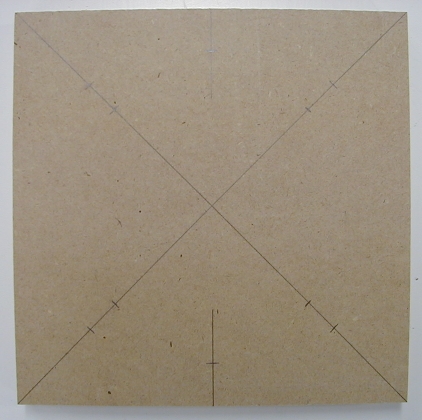
Cabinet Speaker Replacement Using an 8 Inch WooferSafety tip: Be sure to disconnect the power to the game before performing any work! You'll need to remove the playfield glass and raise the playfield to gain access to the existing cabinet speaker; don't forget to remove the pinballs before raising the playfield! You may want to consider removing the playfield from the cabinet. This will provide you with significantly better access to the cabinet bottom panel than you would get by simply raising the playfield - especially for early games that use a pivot for the playfield rather than the slide mechanism used in later games. Note: You may need to re-position the printed switch / lamp matrix information sheet if it is stapled to the cabinet bottom panel. Hint: In the sections below you'll need to find the center of a square. It's very easy to do this by drawing diagonal lines from each corner of the square to the opposite corner using a straight edge and a pencil. The point where the two lines intersect to form an "X" is the center of the square. Safety tip: Wear eye protection when using power tools! A dust mask will come in handy for the operations that generate lots of dust. Remove the Existing SpeakerDisconnect the black and black-yellow wires that are connected to the cabinet speaker; the wires end in quick-disconnect terminals so you can simply pull them off the speaker terminals. The speaker is held in place by four nuts; remove the nuts and washers, and then remove the old cabinet speaker and discard it. Save the nuts and washers in case you can re-use them with the woofer; ditto for the plastic speaker grille. Options for Cabinet Speaker MountingNote: On early WPC games (such as Funhouse or Harley Davidson) the cabinet speaker is mounted directly to the cabinet bottom panel; there is no separate wooden mounting block as is the case for the later games. In these cases you can choose to install a new mounting block for the new speaker if you'd like; that's the course I'd personally take. There are three options for mounting the replacement speaker. You can remove the existing mounting block, and either fabricate a new mounting block or mount the speaker directly to the cabinet bottom panel. You can also mount the speaker directly to the existing mounting block using an adapter plate. The disadvantage to the adapter plate is that the smaller opening in the cabinet bottom will restrict the airflow of the new speaker by some thirty percent; I haven't run any tests to determine exactly how this would affect sound reproduction. Perhaps more importantly, an adapter plate raises the new speaker at least 3/4 inch higher above the cabinet bottom panel, which increases the chances the speaker magnet will bump into an under-playfield assembly of some type. This can present a problem on some games; check the game-specific information section for details on games with known cabinet speaker clearance issues. Either way, the choice is up to you. If you're going to use an adapter plate you can skip ahead to the section on using an adapter plate. Remove the Existing Mounting BlockThe easiest way to remove the existing mounting block is to insert the tip of a half-inch wide wood chisel in the joint between the bottom of the mounting block and the top surface of the cabinet bottom panel. A sharp rap with a hammer will usually pop the glue joints; you'll have to pry the mounting block upward a bit until the brads that hold the block in place come free of the cabinet bottom. Use the wood chisel to scrape off any left-over glue that remains on the top surface of the cabinet bottom.
Test-fit the length of the speaker screws in the original mounting block to see if you can re-use them for the woofer. Set the original mounting block on a flat surface with the ends of the speaker screws facing upward. Carefully lower the speaker so that one speaker screw enters one speaker mounting hole. If you can see at least 1/4 inch of screw threads projecting above the top surface of the speaker frame you can re-use the original speaker screws; if not, you'll have to obtain longer speaker screws or use T-nuts and machine screws to mount the speaker to the mounting block. Continue based on the mounting option you chose: using a new mounting block or mounting directly to the cabinet bottom panel. Using a New Mounting BlockWe will fabricate a new mounting block sized to accommodate an 8 inch speaker. Fabricate the New Mounting BlockThe new mounting block is fabricated from 1/2 inch thick MDF board. The mounting block will be 10 inches square, and will have a circular hole cut in the center. The exact size of the hole will be listed in the specification sheet for the woofer that you're using: look for the speaker mounting hole size. Here is a diagram of the mounting block we're going to fabricate:
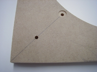
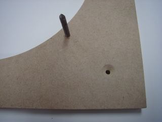
Note: The exact location of the speaker mounting hardware depends on the specific speaker that you are using; see the instructions below for details. Cut a piece of 1/2 inch thick MDF board 10 inches square. A table saw is the best tool for this job; if you don't have a table saw you can use a portable circular saw. You can also have your local lumber dealer cut some pieces of MDF board to size for you. MDF board is relatively inexpensive, and it usually costs an extra quarter or fifty cents per cut for the lumber dealer to cut the MDF board to size. Use the diagonal line method described above to locate the exact center of the new mounting block. Consult the speaker specification sheet for the speaker mounting hardware spacing; if it's not listed simply measure from the center of one mounting hole on the speaker to the one opposite it. For reference, 7-3/4 inches is a common mounting hardware spacing for an 8 inch woofer. Divide this distance in half, and make a mark on the mounting block on each diagonal line this distance from the center of the square (four marks total). The speaker mounting hardware will be installed at these locations. Double-check the markings by measuring the distance from one mark to the one opposite it; the distance should match the speaker mounting hole spacing. Make another set of marks on the mounting block on each diagonal line about 1-1/2 inches from each corner (four marks total). Screws will be placed here to fasten the mounting block to the cabinet bottom panel. Consult the speaker specification sheet for the speaker mounting hole size; if it's not listed simply measure across the outside edges of the speaker cone surround. For reference, 7-1/8 inches diameter is a common mounting hole size for an 8 inch woofer. If you're using a circle cutter adjust it for the proper size cutout. Be sure to securely clamp the MDF board to the table of the drill press before starting the drill press! Position the pilot bit where the two diagonal lines intersect and slowly advance the circle cutter until it has cut through the entire thickness of the board. Stop as soon as the cutout section of MDF board starts to spin around with the circle cutter bit. If you're using a jig or sabre saw, use a compass to mark an appropriately sized circle centered on the mounting block. Drill a pilot hole for the saw blade just inside the circle, then carefully cut along the line using the jig or sabre saw. Use a fine-toothed wood cutting blade so the cutout edges are smooth, and favor the inside edge of the line when cutting so the cutout isn't too large. Take your time and try to make the cutout as close to a perfect circle as you can. Next we'll drill holes in the mounting block for the speaker mounting hardware. If you're using speaker screws to mount the woofer the holes should be just slightly larger than the diameter of the threaded portion of the screw; 3/16 inch diameter is ideal for a #8 speaker screw. If you're using T-nuts and machine screws to mount the woofer the holes should be just slightly smaller than the outside diameter of the central portion of the T-nut; 7/32 inch diameter is ideal for a #8 T-nut. After you've drilled the mounting holes use a 5/8 inch Forstner drill bit to make a shallow recess around each mounting hole so the new mounting block will lie flat on the cabinet bottom panel (the head of the speaker screw or the T-nut "lip" will fit into this recess). Drill on the side of the mounting block with the pencil lines; that way the exposed top face of the mounting block looks neater. We also need to drill holes for the screws that will fasten the new mounting block to the cabinet bottom panel; you can use #8 flat head wood screws that are 3/4 or 7/8 inch in length. A 3/16 inch diameter hole is ideal for a #8 screw. After drilling the holes you should use a countersink bit to make a conical recess for the screw heads in the new mounting block. Use a hammer to tap the speaker screws or T-nuts in place from the bottom side of the mounting block; be sure they don't protrude above the bottom surface of the mounting block. Test fit the woofer on the new mounting block to be sure the mounting hardware is located correctly; it's easier to make adjustments now than after you've fastened the new mounting block to the cabinet bottom panel! Here's how the recessed and countersunk holes should look; a speaker screw is visible in the image on the right:
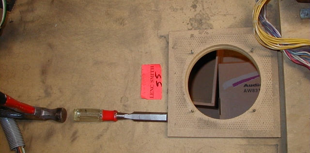
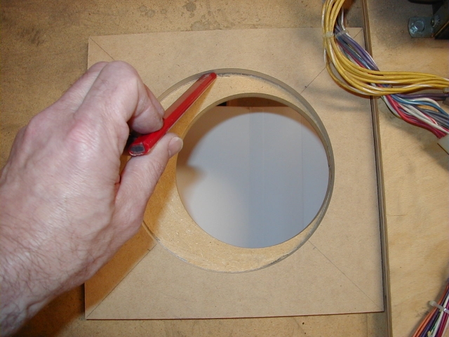
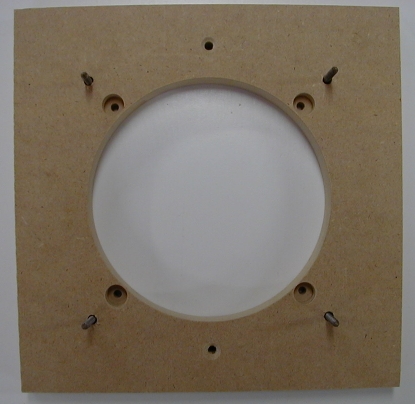
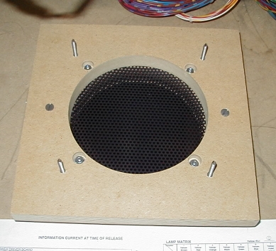
Rough-cut the Hole in the Cabinet Bottom PanelPosition the new mounting block on the bottom of the cabinet, spaced evenly from side to side, with the front edge of the cutout just touching the front edge of the existing cutout in the cabinet bottom panel. Leave at least 1/16th of an inch space between the front edge of the mounting block and the back edge of the wooden cross brace on which the transformer is mounted. Draw around the inside edge of the circular cutout in the new mounting block with a pencil to mark the new cutout on the cabinet bottom. Use an awl or sharp nail to mark the position of the screws that will fasten the mounting block to the cabinet bottom panel.
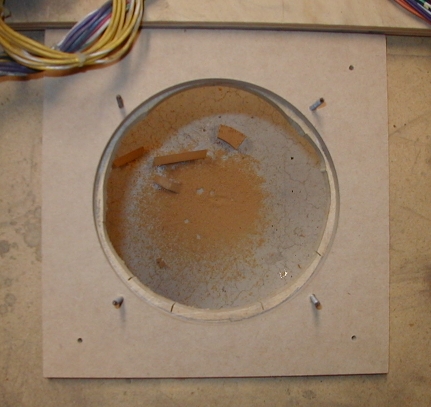
Note: The cabinet front is towards the right in this picture. This picture shows the mounting block before holes were drilled for the speaker mounting hardware. Use a jig saw to cut the excess material about 1/4 inch inside the pencil line. When you're done the cabinet hole should look like this (the new mounting block is placed in approximate position on the cabinet bottom panel):
Fasten the New Mounting Block to the Cabinet Bottom PanelDrill 1/16 inch diameter pilot holes about 1/4 inch deep in the cabinet bottom panel where you marked the position of the new mounting block's mounting screws. Apply a thin layer of carpenter's wood glue to the bottom surface of the new mounting block. Position the new mounting block on the cabinet bottom panel and line up the mounting holes in the block with the pilot holes in the bottom panel. Insert the mounting screws in their holes and tighten the screws securely. Wipe off any glue that squeezes out with a damp paper towel.
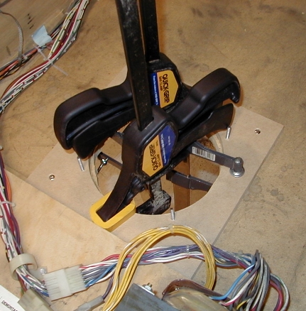
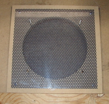
It's not a bad idea to clamp the new mounting block to the cabinet bottom panel until the wood glue dries; about two hours is usually sufficient. Clean Up the Hole in the Cabinet Bottom PanelWe'll use a router and edge trimming bit to clean up the edges of the cabinet cutout; the circular cutout in the new mounting block will serve as a guide for the router bit. Insert the edge trimming bit in the router and adjust the router so the bit protrudes about 3/4 inch from the bottom plate of the router; this depth should place the guide bearing in the center of the new mounting block when the router is inserted from the bottom of the cabinet.
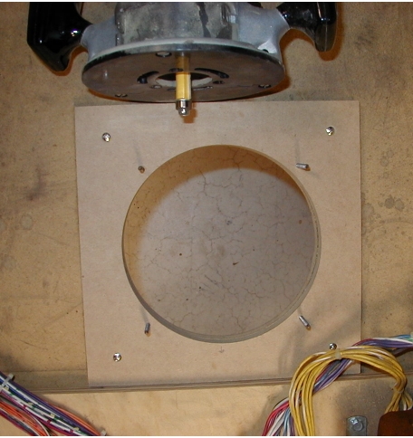
Note: This picture shows the trimmed cabinet cutout; the router is shown resting on the top side of the cabinet bottom so you can see how much of the bit should project from the bottom. The router should be inserted from the bottom side of the cabinet when trimming the cutout. The router will generate quite a bit of sawdust; it's a good idea to have a helper hold a shop vacuum hose near the opening to catch the dust. Continue on to check if you need a spacer. Mounting the Speaker Directly to the Cabinet Bottom PanelYou can use this method if you don't want to fabricate a new mounting block. It won't look quite as "factory" but it requires less wood-working skill. Fabricate a Cutout TemplateTo help mark the cutout and the speaker mounting hardware locations on the cabinet bottom panel we'll make a template from a 10 inch square piece of stiff cardboard. Here is a diagram of the template we're going to fabricate:
Cut a piece of stiff cardboard 10 inches square; use the diagonal line method described above to locate the exact center of the cardboard square. Consult the speaker specification sheet for the speaker mounting hardware spacing; if it's not listed simply measure from the center of one mounting hole to the one opposite it. For reference, 7-3/4 inches is a common mounting hole spacing for an 8 inch woofer. Divide this distance in half, and make a mark on each diagonal line this distance from the point where the two diagonal lines intersect (four marks total). This will be where the speaker mounting screws will be installed. Double-check the markings by measuring from one mark to the one opposite it; the distance should match the speaker mounting hole spacing. Consult the speaker specification sheet for the speaker mounting hole size; if it's not listed simply measure across the outside edges of the speaker cone surround. For reference, 7-1/8 inches diameter is a common mounting hole size for an 8 inch woofer. Use a compass to draw a circle of this size centered on the cardboard square. Cut out the circle marked on the cardboard using an X-Acto knife or a single-edge razor blade. Enlarge the Hole in the Cabinet Bottom PanelPosition the cardboard template on the bottom of the cabinet, spaced evenly from side to side, with the front edge of the cutout just touching the front edge of the existing cutout in the cabinet bottom panel. Tape the template in place temporarily. Use a pencil and draw around the cutout circle to mark the new cutout on the cabinet bottom. Mark the mounting hole positions using an awl or a sharp nail. Remove the template and save it for future use. Drill a pilot hole for the saw blade just inside the circle, and then carefully cut along the line using the jig or sabre saw. Use a fine-toothed wood cutting blade so the cutout edges are smooth, and favor the inside edge of the line when cutting so the cutout isn't too large. Take your time and try to make the cutout as close to a perfect circle as you can. You can smooth the edges of the cutout by wrapping a sheet of medium sand paper around a quart paint can and using that as a sanding block to lightly smooth any imperfections or saw blade marks. Drill holes at the four mounting locations you marked on the cabinet bottom. If you're using speaker screws the holes should be just slightly larger than the diameter of the threaded portion of the screw; 3/16 inch diameter is ideal for a #8 speaker screw. If you're using T-nuts and machine screws to mount the new speaker the holes should be just slightly smaller than the outside diameter of the center portion of the T-nut; 7/32 inch diameter is ideal for a #8 T-nut. Use a hammer to tap the speaker screws or T-nuts in place from the bottom side of the cabinet bottom panel. Continue on to check if you need a spacer. Mounting the Speaker to the Existing Mounting Block with an Adapter PlateNote: I don't recommend this method because the smaller sized cutout in the existing mounting block and cabinet bottom panel will block about thirty percent of the airflow of the new woofer. More significantly, the adapter plate also adds enough height that the new speaker may interfere with under-playfield assemblies on some games. Fabricate the Adapter PlateThe adapter plate is fabricated from 3/4 inch thick MDF board. The adapter plate will be 9 inches square, and will have a 5-1/2 inch diameter circular hole cut in the center. Here is a diagram of the adapter plate we're going to fabricate:
Start by cutting a piece of 3/4 inch thick MDF board 9 inches square. A table saw is the best tool for this job; if you don't have a table saw you can use a portable circular saw. You can also have your local lumber dealer cut some pieces of MDF board to size for you; MDF board is relatively inexpensive, and it usually costs an extra quarter or fifty cents per cut for the lumber dealer to cut the MDF board to size. Use the diagonal line method described above to locate the exact center of the adapter plate. Consult the speaker specification sheet for the speaker mounting hardware spacing; if it's not listed simply measure from the center of one mounting hole on the speaker to the one opposite it. Divide this distance in half, and make a mark on each diagonal line this distance from the center of the square (four marks total). The speaker mounting hardware will be installed at these locations. Make marks on each diagonal line 3-3/32 inch from the center of the square (four marks total). The cabinet speaker mounting block screws will pass through these points. Measure 4-1/2 inches from either the left or right edge of the board and make marks at the top and bottom of the board (two marks total). Draw a line from the top to the bottom of the board. Measure 1 inch from the top and 1 inch from the bottom of the board and make marks on the vertical line at those two points. The adapter plate will be fastened to the cabinet bottom panel via flat head screws through these holes. The adapter plate should look like this once all the layout lines have been drawn:
Now we'll cut the 5-5/8 inch diameter circular hole in the adapter plate. If you're using a circle cutter adjust it for the proper size. Be sure to securely clamp the MDF board to the table of the drill press before starting the drill press! Position the pilot bit where the two diagonal lines intersect and slowly advance the circle cutter until it has cut through the entire thickness of the board. If you're using a jig or sabre saw, use a compass to mark a 5-5/8 inch diameter circle centered on the adapter plate. Drill a pilot hole for the saw blade just inside the circle, then carefully cut along the line using the saw. Use a fine-toothed wood cutting blade so the cutout edges are smooth, and favor the inside edge of the line when cutting so the cutout isn't too large. Next we'll drill holes in the adapter plate for the original mounting block speaker screws. A 3/16 inch diameter hole will provide sufficient clearance and a bit of room for adjustment. After you've drilled the mounting holes use a 1/2 inch Forstner drill bit to make a 3/8 inch deep recess around each mounting hole; this provides room for the nuts that fasten the adapter plate to the existing mounting block. Drill on the side without pencil lines, and be careful not to drill all the way through the adapter plate! We also need to drill 3/16 inch diameter holes in the adapter plate for the screws that will fasten the adapter plate to the cabinet bottom panel. We will use #8-32 x 1-3/4 inch flat head machine screws and #8-32 T-nuts to ensure the original speaker mounting block doesn't break free from the cabinet bottom when the game is moved. After drilling the holes use a countersink bit to make a conical recess for the screw heads in the new mounting block. Now we'll drill holes in the adapter plate for the speaker mounting hardware. If you're using speaker screws to mount the woofer the holes should be just slightly larger than the diameter of the threaded portion of the screw; 3/16 inch diameter is ideal for a #8 speaker screw. If you're using T-nuts and machine screws to mount the new speaker the holes should be just slightly smaller than the outside diameter of the threaded portion of the T-nut; 7/32 inch diameter is ideal for a #8 T-nut. Use the Forstner drill bit to make a shallow recess around each mounting screw hole - be sure to drill on the side of the adapter plate where you've made the pencil lines. The completed adapter plate should look like this:
Use a hammer to tap the speaker screws or T-nuts in place from the bottom side of the adapter plate. Test fit the woofer on the adapter plate to be sure the mounting hardware is located correctly; it's easier to make adjustments now than after you've fastened the adapter plate to the existing mounting block! Mount the Adapter PlatePlace the adapter plate on top of the original mounting block with the speaker screws on the mounting block lined up with the corresponding holes in the adapter plate; be sure the plastic speaker grille is in place. You should position the adapter plate so the two sides near the edges of the plate are located near the left and right side of the mounting plate. Temporarily fasten the adapter plate in place using the original 5/16 inch KEPS nuts and #6 washers. Use a 3/16 inch diameter drill bit to drill holes positioned at the two outside holes in the adapter plate; drill through the original mounting block and the cabinet bottom panel. Remove the adapter plate and enlarge the holes in the cabinet bottom panel (from the bottom of the cabinet) using a 7/32 inch diameter drill bit. Use a hammer to tap two #8-32 T-nuts into the bottom of the cabinet. Replace the adapter plate on the original mounting block; the original plastic speaker grille should be sandwiched between the original mounting block and the adapter plate. Fasten the adapter plate to the mounting block with the washers and nuts you removed from the original cabinet speaker. Fasten the adapter plate and original mounting block to the cabinet bottom panel using two #8-32 x 1-3/4 inch flat head machine screws.
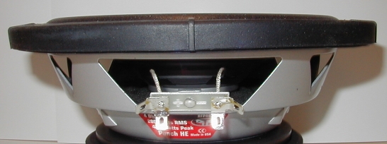
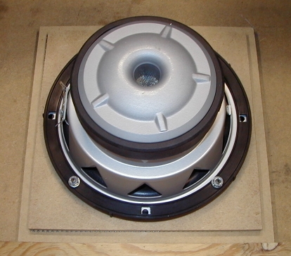
Check if You Will Need a SpacerThe surround on some woofers may project beyond the mounting plane of the speaker. If this is the case for the speaker you've selected you'll need to fabricate a spacer to space the woofer back from the speaker grille to provide enough clearance for the surround. This picture shows a surround that projects about 1/8 inch above the speaker mounting plane (this is a Rockford-Fosgate RFP4408 woofer):
A 1/4 inch thick spacer is usually sufficient, but you'll have to check your specific model of speaker to be sure. You may choose to just skip the plastic speaker grille instead of using a spacer. I wouldn't recommend this as it exposes the speaker to possible damage from an errant foot or knee when moving the game. If you don't need a spacer continue on to prepare the new plastic speaker grille. Fabricate a SpacerThe spacer is fabricated from 1/4 inch thick MDF board. The spacer will be 9 inches square, and will have a circular hole cut in the center. The exact size of the hole will be listed in the specification sheet for the woofer that you're using: look for the speaker mounting hole size. Here is a diagram of the spacer we're going to fabricate:
Note: The exact location of the speaker mounting hardware depends on the specific speaker that you are using; see the instructions below for details. Cut a piece of 1/4 inch thick MDF board 9 inches square. A table saw is the best tool for this job; if you don't have a table saw you can use a portable circular saw. You can also have your local lumber dealer cut some pieces of MDF board to size for you. MDF board is relatively inexpensive, and it usually costs an extra quarter or fifty cents per cut for the lumber dealer to cut the MDF board to size. Use the diagonal line method described above to locate the exact center of the spacer. Consult the speaker specification sheet for the speaker mounting hardware spacing; if it's not listed simply measure from the center of one mounting hole on the speaker to the one opposite it. For reference, 7-3/4 inches is a common mounting hardware spacing for an 8 inch woofer. Divide this distance in half, and make a mark on the spacer on each diagonal line this distance from the center of the square (four marks total). The speaker mounting hardware will pass through these locations. Double-check the markings by measuring the distance from one mark to the one opposite it; the distance should match the speaker mounting hole spacing. Consult the speaker specification sheet for the speaker mounting hole size; if it's not listed simply measure across the outside edges of the speaker cone surround. For reference, 7-1/8 inches diameter is a common mounting hole size for an 8 inch woofer. If you're using a circle cutter adjust it for the proper size cutout. Be sure to securely clamp the MDF board to the table of the drill press before starting the drill press! Position the pilot bit where the two diagonal lines intersect and slowly advance the circle cutter until it has cut through the entire thickness of the board. Stop as soon as the cutout section of MDF board starts to spin around with the circle cutter bit.
Note: You may want to use a 1/4 inch brad-point drill bit to make a pilot hole before using the circle cutter; the pilot bit on the circle cutter is a standard drill bit that is a little tough to align exactly even with the center lines on the template. The completed spacer should look like this:
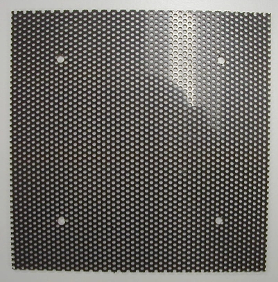
Drill Mounting Holes in the New Plastic Speaker GrilleIf you're using a new mounting block or mounting the woofer directly to the cabinet bottom panel you'll need a new piece of 9 inch square plastic speaker grille to protect the woofer from damage. If you're using an adapter plate to mount the woofer to the existing mounting block you will re-use the old speaker grille; skip ahead to the section on mounting the woofer. Apply two strips of masking tape diagonally across the top surface of a new piece of 9 inch square plastic speaker grille. Use the diagonal line method described above to locate the exact center of the plastic speaker grille. Consult the speaker specification sheet for the speaker mounting hardware spacing; if it's not listed simply measure from the center of one mounting hole on the speaker to the one opposite it. For reference, 7-3/4 inches is a common mounting hardware spacing for an 8 inch woofer. Divide this distance in half, and make a mark on the plastic speaker grille on each diagonal line this distance from the center of the square (four marks total). Drill 1/4 inch diameter holes at these four points, and then remove the masking tape. The completed speaker grille should look like this:
Mount the WooferThe procedures differ slightly here based on the mounting option you chose. Using a New Mounting Block or Mounting to the Cabinet Bottom PanelPosition the plastic speaker grille so the mounting holes line up with the the speaker screws or T-nuts. If your woofer requires a spacer that is placed over the speaker mounting hardware. Lower the new woofer into place, install the appropriate mounting hardware, and carefully tighten the nuts or machine screws until the new woofer is held firmly in place. Don't over-tighten the mounting hardware! Using an Adapter PlateMount the woofer to the adapter plate using washers and nuts or machine screws, depending on the mounting hardware you picked (speaker screws or T-nuts); if your woofer requires a spacer place that on top of the adapter plate first.
Lower the new woofer into place, install the appropriate mounting hardware, and carefully tighten the nuts or machine screws until the new woofer is held firmly in place. Don't over-tighten the mounting hardware!
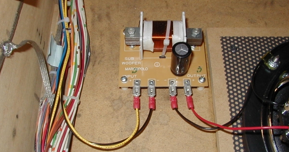
Mount the Crossover or InductorIf you are using a crossover or inductor with the cabinet speaker it can be mounted to the bottom panel of the cabinet in the general vicinity of the cabinet speaker. A good location is between the cabinet speaker mounting block and the left wall of the cabinet; that area is generally free of wires or other obstructions. This picture shows the Pyramid CR-19 crossover mounted as described:
If you'd like you can use some short plastic spacers to raise the crossover a slight distance above the cabinet bottom panel. You can use Williams part number 03-8022-1 spacers (available from Bay Area Amusements) or Keystone model 8837 spacers. In either case you'll have to enlarge the four mounting holes in the corners of the crossover. Inductors with an "air core" (no spool or bobbin) can be mounted using PVC electrical conduit clamps; clamps sized for 1-1/2 inch conduit would generally work out, but that depends on the physical size of the inductor. Don't use metal clamps to mount the inductor; that can damage the insulation on the wire. An inductor with a spool or bobbin can generally be mounted via a dowel and screw sized to fit the inside diameter of the spool.
NEXT: wiring replacement speakers HOME: WPC speaker replacement
Copyright © 2005 by Joseph A. Dziedzic. All rights reserved. |